
Liquid chromatography (LC) is essential to many scientific & quality laboratories. HPLC is a widely used analytical technique in the field of chemistry, biochemistry, and pharmaceuticals. It is not without its challenges, and troubleshooting can be a significant part of the work of an LC analyst. Every HPLC consists of the same basic components. Problems can take place in each component can change the overall performance and also will consume more cost to recover the problems. Troubleshooting HPLC instrumentation and separations requires a fundamental understanding of how the instrument functions and how the separation works. HPLC can experience failure of system suitability, peak characteristics, and contamination. System suitability like tailing factor, resolution, theoretical plates, peak shape, baseline disturbance (drift and noise), sensitivity (s/n), selectivity (RT & RRT of analytes), and precision (% relative standard deviation). Failures apart from peak characteristics such as carryover can impact the accuracy and reliability of the results.
The below table summarizes a few LC system modules’ problems, their impact, and solution
LC system modules’ problems, impacts, and solution
|
System Module / Problems |
Impact |
Solutions |
|
Reservoir |
1) Blocked inlet frit 2) Gas bubbles |
1) Replace periodically (3–6 months) 2) Filter the mobile phase through a 0.22- micron filter, Degas the mobile phase |
|
Pump A sure sign of a leak is a buildup of salts at a pump connection |
1) Leaks at pump fittings or seals will result in poor chromatography. 2) Erratic retention times, noisy baselines, or spikes in the hromatogram. |
1) Buffer salts should be flushed from the system daily with fresh water. Tighten or replace the fitting. Cut the tubing and replace the ferrule; disassemble the fitting, rinse, and reassemble. 2) Replace detector seal or gaskets. Replace valve rotor. Replace pump seal; check piston for scratches and, if necessary, replace. Run the HPLC system constantly at low flow rates (e.g. 1 ml/min) to avoid crystallization effects. |
|
Check valves 1) Problems can occur to check valves in the pump head 2) Highly concentrated salts 3) Caustic mobile phases can reduce pump seal efficiency. 4) Prolonged use of ion-pair reagents has a lubricating effect on the pump pistons Leeds to small leaks at the seal. |
1) Pump is not able to produce a constant flow/pressure, 2) If this does not work, valves and clean them in an ultrasonic bath using isopropanol. 3) Then refit the check valves in the pump head. Be sure that the valves are inserted in the right direction. |
1) Clean the check valves with isopropanol. 2) If not dismantle the check 3) Clean it in an ultrasonic bath using isopropanol. Then refit the check valves in the pump head. Be sure that the valves are inserted in the right direction. |
|
Injector/injection problems: The injector rapidly introduces the sample into the system with minimal disruption of the solvent flow. variable loop, fixed loop, and syringe-type injectors. |
1) Leaks, plugged capillary tubing, worn seals) 2) Variable peak heights, split peaks. 3) Broad peaks can be caused by incompletely filled sample loops, incompatibility of the injection solvent with the mobile phase, or poor sample solubility. |
1) Use a column filter unit to prevent plugging of the column frit due to physical degradation of the injector seal. 2) Possible, dissolve and inject samples in the mobile phase 3) Make sure that the wash solution is compatible with and weaker than the mobile phase. |
|
Detector problems: fixed and variable wavelength ultraviolet spectrophotometers, refractive index, and conductivity detectors. Electrochemical and fluorescence detectors are less frequently used Electrical. For electrical problems, we should contact the instrument manufacturer. Mechanical or optical problems can usually be traced to the flow cell. leaks, air bubbles, and cell contamination. in refractive index detectors – are sensitive to pressure. Old or defective lamps |
Faulty or reversed cable connections The incorrect detector rise time, gain, or attenuation will reduce sensitivity and peak height. No peaks or very small peaks Usually produce spikes, baseline noise or drift in the chromatograms or low sensitivity. |
Usually produce spikes, baseline noise or drift in the chromatograms or low sensitivity. Check detector, Check connections, Check sample. Be sure it does not deteriorate. Check for bubbles in the vials & Check attenuation. Check gain |
|
HPLC column: The physicochemical parameter and understanding the compatibility with sample and instrumentation is the key stapes to avid the problems in separation |
Steady High Pressure & Steady Low Pressure |
Back flush column (if permitted) |
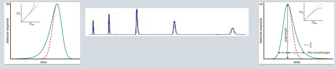
Peak tailing:
Peak tailing occurs when the peak asymmetry factor (As) is greater than 1.2, Asymmetry factors: 0.9–1.2 acceptable As = B / A; where B = peak width after the peak center at 10% peak height; and A = peak width at baseline before the peak center, Peak asymmetry, and peak tailing factor relationship. Peak Asymmetry Factor (at 10%) & Peak Tailing Factor (at 5%), peak width at 5% of the peak height,
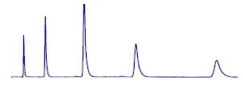
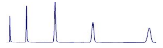
Regular peaks/ Gaussian peak
| Tailing and Fronting of Chromatographic Peaks | ||||||||||||||||
Regular peaks/ Gaussian peak |
||||||||||||||||
| Types of peaks | Representative chromatogram | |||||||||||||||
|
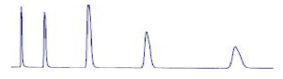
Tailing Peaks can be caused by packing, or by having a sample that is too viscous. Some sites on the stationary phase retain the solute more strongly than other sites |
problematic peak (Peak tailing) |
|
||||||||||||||
|
Possible cause |
Solution |
|
|
1. Polar component interactions with any ionized residual silanol. |
Operate at a lower pH: As silanol groups are acidic, secondary interactions can be minimized by performing chromatographic separation at a lower pH. Use a highly deactivated column: End-capping is a process whereby residual silanol groups are treated to convert them to substantially less polar surface functional groups Trimethylchlorosilane (TMCS) Hexamethyldisilane (HMDS) |
|
|
2. Consider the possibility of column bed deformation: |
Assess this by simply diluting the sample x10 and re-assess the peak shapes Use a sample clean-up procedure: Solid Phase Extraction (SPE) can be used to remove any interfering contaminants. |
|
|
3. Consider the possibility of column bed deformation: The partially blocked inlet frit are the root cause(s). |
Substituting the column will quickly confirm the problem. If a void is suspected, reverse the column, disconnect it from the detector, and wash in 100% strong solvent (at least 10) |
|
|
4. Work at high pH when analyzing basic compounds: it is usually only possible to use pH to suppress acid ionization, as base ionization typically requires pH values of greater than 8, at which pH silica dissolution can occur. |
Use the robust stationary phase with a higher pH range |
|
|
Peak Fronting is often caused by column overload or overpacking. most often is the result of overloading the column with sample |
Peak Fronting |
Use a higher-capacity stationary phase. increase column diameter. Decrease sample amount. Replace or repack the column |
|
Negative peak Sample solvent and mobile phase differ greatly in composition |
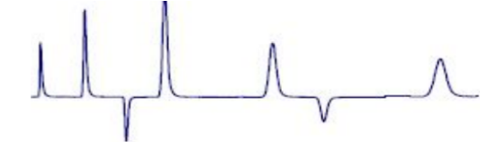
Negative peak |
Use a mobile phase with a lower refractive index. Adjust or change sample solvent. Dilute the sample in the mobile phase whenever possible. Change the UV wavelength or use a mobile phase that does not adsorb at the chosen wavelength. |
|
Broad peaks: Mobile phase composition changed. Mobile phase flow rate too low Leak (especially between column and detector). Buffer concentration too low. Guard column contaminated/worn out |
Broad peaks: |
1. Prepare a new mobile phase. 2. Adjust flow rate. 3. Check the system for loose fittings. Check the pump for leaks, salt buildup, and unusual noises. Change pump seals if necessary. 4. Adjust settings. 5. Increase concentration. 6. Replace the guard column. |
|
Ghost peak: Contamination in injector or column, tress contamination in mobile phase |

Ghost peak: 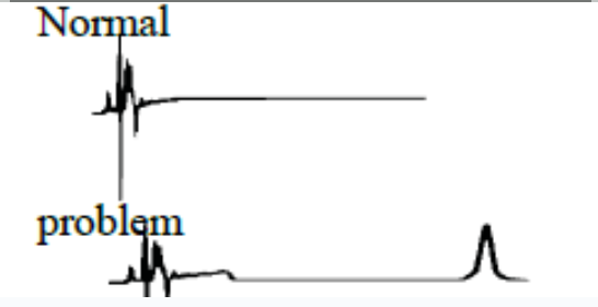 |
Flush injector, run strong solvent through the column to remove late eluters. Include final wash. Step in gradient analysis, to Remove strongly retained compounds. Use an LC system minimum pressure change during the load and inject steps Ghost Guard / Ghost trap helps by removing particulate contaminants and highly absorptive compounds from samples, prolonging column life |
|
All peaks doubling / Splitting |
The most common cause of peak doubling can be either blockage prior to the column or guard voiding |
Wash the column reveresed direction, draint the eluent without passing to detector. Change the column. |
|
Change in Selectivity: |
1. Increase or decrease solvent ionic Strength, pH, or additive concentration (especially affects ionic solutes). 2. Column changed; new column has different selectivity from that of old Column. 3. Sample injected in incorrect solvent or excessive amount (100-200 μL) of strong solvent. 4. Column temperature change |
1. Check the make-up of the mobile phase. 2. Confirm the identity of column packing. For reproducible analyses, use the same column type. Establish whether change took place gradually. If so, the bonded phase may have been stripped. 3. Adjust solvent. Whenever possible, inject the sample in the mobile phase. 4. Adjust the temperature. If needed, a use column oven to maintain a constant temperature.
|
The Effect of failure Tailing, symmetry, peak shape, broadening, splitting, all these peak characteristics loss of the separation, accuracy, sensitivity, and selectivity of the analytes. The most significant impacts in the case of trace analysis.
The below table summarizes common problems, possible causes, and required action and solution
|
Problem |
Possible cause |
Required corrections / Solutions |
|
Change in retention time |
1. Contamination buildup 2. Equilibration time insufficient for gradient run 3. First few injections - active sites 4. Non-effective online mobile-phase mixing 5. Evaporation or stability mobile phase component 6. Column temperature fluctuation |
1. Flush the column occasionally with a strong solvent 2. Required at least 10 column volumes equilibration to gradient regeneration or after solvent changes 3. Condition the column by injecting the concentrated sample 4. Ensure the gradient system is delivering a constant composition; compare with manually prepared mobile phase; partially premix mobile phase 5. Cover solvent reservoirs; use less-vigorous helium purging; prepare the fresh mobile phase 6. Thermostat or insulate column; ensure laboratory temperature is constant. |
|
Slow column equilibration time |
Reversed-phase ion pairing - long chain ion pairing reagents require longer equilibration time |
Use shorter and high pure alkyl chain length |
|
Void Time noise |
Air bubbles in the mobile phase Positive-negative - difference in the refractive index of injection solvent and mobile phase |
Degas or use a back pressure restrictor on the detector Use the mobile phase as a diluent |
|
Decreasing Retention Times |
1. Active sites on column packing 2. Column overloaded 3. Increasing flow rate 4. Loss of bonded stationary phase or base silica 5. Fluctuation column temperature |
1. Use MP modifier, basic compounds, or increase buffer strength; use higher coverage column packing 2. Use less sample size, use larger-diameter column. 3. Check and reset the pump flow rate. 4. Use mobile-phase pH between pH 2 and pH 8 5. Thermostat or insulate column; ensure laboratory temperature is constant |
|
Increasing Retention Times |
1. Decreasing flow rate 2. Changing the mobile-phase composition 3. Loss of bonded stationary phase |
1. Check and reset pump flow rate; check for pump cavitation; check for leaking pump seals and other leaks in the system 2. Cover solvent reservoirs; ensure that the gradient system is delivering the correct composition. 3. Use mobile-phase pH between pH 2 and pH 8 |
|
System |
Possible cause |
Impact |
|
Column Issues |
Column contamination, degradation, or damage Use end-capped/base-deactivated columns for analyzing basic compounds |
Column contamination, degradation, or damage. Significant effect on the tailing factor |
|
Mobile Phase Issues |
Incorrect pH, buffer concentration, or solvent composition |
Impact separation and lead to resolution failure |
|
Sample Preparation: |
Sample preparation can lead to issues such as sample degradation or contamination |
Impact separation and resolution, results of tress analyte content. |
|
Instrumentation Issues: |
Issues such as detector malfunctions, flow rate fluctuations, or system leaks |
Impact the accuracy of HPLC results. |
|
Method Development Issues: |
Requires careful consideration of factors such as column selection, mobile phase composition, and sample preparation |
Failure to optimize these factors can lead to resolution failure. |
|
Operator Error: |
Incorrect injection volume, incorrect mobile phase flow rate, or incorrect column temperature |
Impact separation and resolution |
|
Maintain and replace columns, optimize mobile phase composition, and sample preparation, and carefully consider all factors involved in method development. Additionally, operators must be properly trained and vigilant in their use of HPLC systems to avoid common errors that can impact separation and resolution. |
||
|
Improper selection |
Results |
Prominent selection |
|
Improper column selection: selected based on the sample characteristics and the separation requirements |
To incomplete separation or co-elution of compounds, resulting in inaccurate or unreliable results |
Selection and optimization of the mobile phase is necessary to achieve successful separation |
|
Incorrect mobile phase composition |
The wrong column can result in poor peak separation, decreased resolution, and low sensitivity |
Thoroughly understand the sample and column properties to ensure optimal separation and detection. |
|
Inadequate sample preparation |
Failure to properly prepare the sample, such as insufficient extraction or purification, can result in low signal intensity, poor resolution, or even inaccurate quantification significantly affect the accuracy and precision of the results |
Adequate sample preparation is essential for reproducible and reliable HPLC results |
|
Poor instrument maintenance |
Regular maintenance and calibration of the HPLC system are essential to ensure accurate and reliable results Neglecting routine maintenance and calibration can lead to poor peak shape, drift in retention times, or decreased sensitivity |
Follow the manufacturer's recommended maintenance and calibration schedule to ensure optimal system performance |
Concussion: The chromatographic separation is significantly impacted by minute variations in any components of the system, environment, process, and practices. The harmonization of the component, system, process, and practices will smoothly run the routine analysis, development, validation, method transfer and quality control activity across the sites. The current practices, training and implementation is the at most paramount of all analytical process smoothness of testing and quality control monitoring.
About Author:
Sunil Dattatray Pawar is currently employed as a specialist in the Analytical R&D department at Aurigene. Prior to this role, he spent ten years at Dr. Reddy's Laboratories, where he held various positions. Sunil's expertise includes developing analytical methods, identifying impurities, using anion exchange chromatography, managing plant executions, supporting DMF filings, and addressing regulatory queries.
Latest Posts
Transforming Drug Discovery with Aurigene.AI

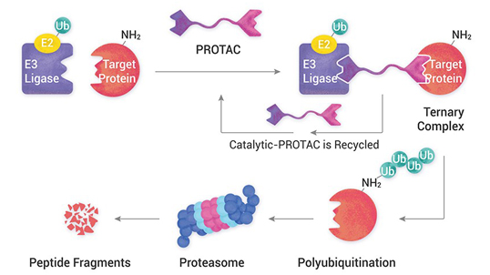
PROTACs: Research for a life without cancer

Good practices in non-clinical toxicology assessment to accelerate IND and NDA Submissions
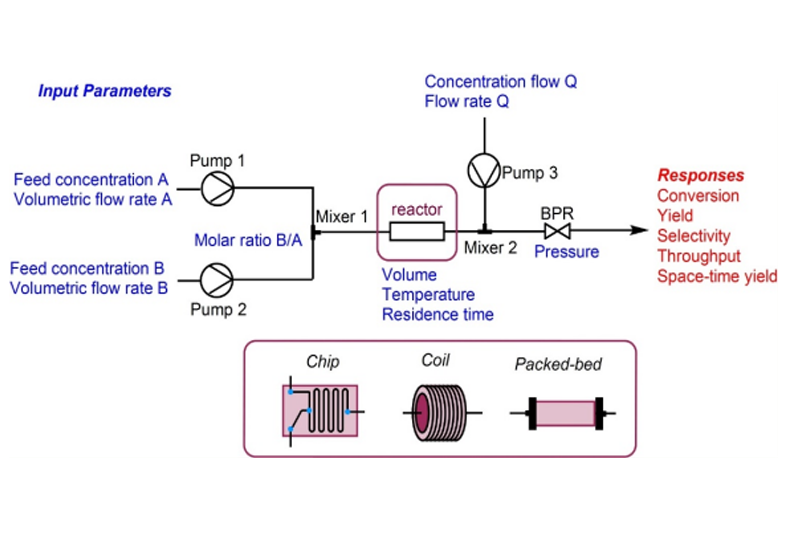
Continuous Flow Chemistry: A Game-Changer for Pharmaceutical Production

mRNA Technology and the Brief History of New Vaccine

Advancement in personalized medicine and how the CRDMO industry is part of the solution

Immuno Oncology - Therapies and Challenges

HPAPI Development at a Glance
You are about to leave Aurigene Pharmaceutical Services and affiliates website. Aurigene Pharmaceutical Services assumes no responsibility for the information presented on the external website or any further links from such sites. These links are presented to you only as a convenience, and the inclusion of any link does not imply endorsement by Aurigene Pharmaceutical Services.
If you wish to continue to this external website, click Proceed.


Leaving already?
Don't forget to join us at
CPHI Worldwide 2023.
October 24th-26th, 2023 | Barcelona, Spain
Get ready to accelerate your drug’s journey to the market
Add new comment